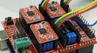
Wiring. (cnc shield based)
After successfully programming the Arduino and setting up the necessary hardware components, it's time to tackle the wiring phase of your DIY CO2 laser cutter project. Wiring plays a crucial role in ensuring proper communication and power distribution throughout the system. Here's an overview of what you'll need and the steps to follow:
#1 Electrical Components:
Gather the required electrical components, including wires, connectors, terminal blocks, and any additional components specific to your laser cutter design.
Power Supply:
For the laser tube, we already have a high-voltage power supply, but we also need a 12-24 volt power supply to power the stepper motors and any other additional components you might incorporate as time goes by.
Wiring Diagram:
Wiring the machine has a few separate stages. We have the low-voltage part (for stepper motors and such), the high-voltage part for the water pump, fume exhaust, etc., and we have the really high-voltage part (25 kV) to ignite the laser tube. This part should not be underestimated. Always triple-check your safety measures before you start working.
Stepper motors need power to move. Usually, you can get away with using a decent PC tower power supply or something more advanced if desired. However, it is important to ensure stable power for reliable motor performance.
The wires of the stepper motors, typically four wires for two coils, will be connected to the corresponding pins on the CNC shield: A1, B1, A2, and B2. To determine which two wires belong to the same coil in the stepper motor, you can perform a simple test. Connect two wires of the motor together and observe the rotor. If the rotor turns with more resistance when touched compared to when it is not touched, you have found the coil.
When connecting the stepper motor wires to the board, you may need to switch their positions to achieve the desired direction of rotation. By swapping the wire connections, you can reverse the polarity and control the motor's movement in the desired direction. This adjustment allows you to fine-tune the motor's behavior according to your specific requirements.