Start building !
If you want to start building something, you need a plan, or a plan comes together during the build. Usually, more experienced makers will design first in a CAD program, make a bill of materials, cut everything to size, and add features before they start building. On the other hand, less experienced makers usually build on the fly. That's how I started making things back in the day. I had a general idea and started building with the materials that I had on hand. This method greatly helps in developing your problem-solving skills in manufacturing something. Also, a good rule is not to avoid making mistakes but to ensure that others don't notice any mistakes that were made.
To motivate kids start making this is a great example

Size doe's mather
The size of my machine was chosen based on the stock material I had available. I had a few meters of box section measuring approximately 2 inches (50mm) x 1 inch (25mm) x 0.16 inches (4mm), and I decided that I wanted a cutting area of at least 23.6 inches (600mm) x 23.6 inches (600mm).
I arrived at this size while considering that I was going to use a 45-watt laser tube initially. It's important to remember that when the laser head is cutting in the bottom right corner, the beam has to travel a considerable distance, resulting in power loss. To ensure optimal cutting power throughout the working area, it's best not to exceed the recommended size for this power rating (approximately 23.6 inches x 23.6 inches).
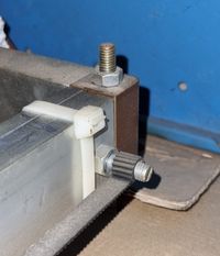
I drew up some simple corner parts to construct a square frame with the 2 inches (50mm) x 1 inch (25mm) box section I had lying around. Additionally, I designed some straightforward carriages to mount the bearings on, which will roll along the surface of the box section. (See pictures below.) The main objective is to create a frame with rollers that can move smoothly in both the X and Y positions. The most common way to achieve this, using readily available materials, is by using extruded aluminum. It comes in various shapes and sizes, and often it is compatible with specific roller bearings that fit into the profile of the extrusion. (See link below.)
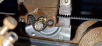
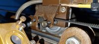
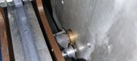
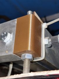
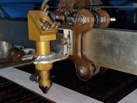
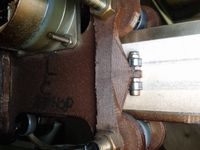
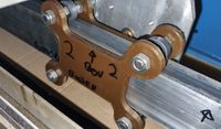
The bearings I used for this build are similar to the ones found in skateboard wheels (approximately 20mm x 7mm with an 8mm hole). There are many different sizes of bearings available, but that is too much information to delve into in this discussion. In theory, the bearing supports are scalable, so it may be possible to adapt this design to fit the box section you have on hand. It doesn't necessarily have to be 3D printed, but I'm using this method to demonstrate the principle of a gantry that can smoothly roll along its surface to the desired position using stepper motors.
Movement
The Gantry needs to move. and to do that we need to control thestepper mothers that we have chosen to use. usualy 4 wire bipolar stepper motors. they are build with 2 coils and a rotor, my choiche of control was an arduino uno with a compatible cnc shield. this is sufficient enouch to move a gantry that only carrys a laserhead and has no such tings as cutting load and so on.
First off all we need to program the arduino with a firmware . these can usualy be found on github or a quick google search . for this build we use the firmware GRBL in combination with the freeware LaserGRBL. this is a simple and free program to control your laser and send gcodes and jobs.
for uploading we need arduino IDE, this is also free to download and use.
Install Arduino IDE:
Download and install the latest version of Arduino IDE from the official Arduino website
(https://www.arduino.cc/en/software)
Follow the installation instructions for your operating system.
Connect Arduino Uno:
Connect your Arduino Uno board to your computer using a USB cable.
Ensure that the board is recognized by your computer, and the appropriate drivers are installed if necessary.
Download GRBL:
Open your web browser and navigate to the official GRBL repository on GitHub (https://github.com/grbl/grbl).
Click on the "Code" button and select "Download ZIP" to download the latest GRBL source code as a zip file.
Extract the contents of the zip file to a location on your computer.
Open Arduino IDE:
Launch the Arduino IDE that you installed earlier.
Configure Arduino IDE:
Go to "File" > "Preferences" in the Arduino IDE.
In the "Additional Boards Manager URLs" field, enter the following URL: https://github.com/gnea/grbl/releases/download/1.1f/arduino-1.8.7-grbl-1.1f.zip
Click "OK" to save the preferences.
Install GRBL Library:
Go to "Tools" > "Board" > "Boards Manager" in the Arduino IDE.
In the Boards Manager, search for "grbl".
Find "grbl" in the search results and click the "Install" button.
Wait for the installation to complete.
Select Board and Port:
Go to "Tools" > "Board" and select "Arduino Uno".
Go to "Tools" > "Port" and select the port to which your Arduino Uno is connected.
Upload GRBL Firmware:
Open the extracted GRBL source code folder.
Navigate to the "grbl" folder within it.
Double-click on the "grbl.ino" file. This will open the GRBL firmware in the Arduino IDE.
Click on the "Upload" button to compile and upload the GRBL firmware to your Arduino Uno.
Verify Communication:
Open the Serial Monitor in the Arduino IDE by clicking on the magnifying glass icon in the top right corner.
Set the baud rate to 115200.
Ensure that the Serial Monitor is set to "Newline" for line endings.
You should see the GRBL firmware version and other information indicating successful communication with the Arduino Uno.
Wiring
Your stepper motors need to be wired to the Arduino CNC shield. This is a simple process. What I usually do first is to identify the wires that belong to the same coil. To do this, connect the wires together and twist the motor axle. If it is harder to turn, then you have identified a coil.
The four wires are typically labeled A+, A-, B+, and B-. These wires correspond to two coils within the stepper motor. The corresponding pins should be marked on your CNC shield.
(Make sure you have a decent power supply for the stepper motors that corresponds to their power consumption.)
I don't use physical endstops in my machine. Instead, I zero the head each time I start at a specific position. However, if you will be using endstops, always double-check the wiring for polarity (+, -) and the signal pin (S). If you hook these up incorrectly, there is a risk of damaging your electronics, and the magic smoke might escape. I will provide more information on setting up endstops, including steps for calibrating the steps per unit.
If you will be using a blue Chinese power supply, keep in mind that the signal pin needs to be inverted using a signal inverter. The default state of the pin is high, and the laser would be continuously triggered with faults lower than that. I will provide a separate section on how to make a signal inverter using affordable components.